Effectiveness of aerated static pile composting depends largely on the aeration system, which can comprise a large portion of the facility’s cost and energy use. Part II
Tom Gibson and Craig Coker
BioCycle February 2013, Vol. 54, No. 2, p. 24
Aerated static pile (ASP) composting is increasing in usage in the U.S. composting industry due to the potential for better process and odor control and, when covered, also for potential improvements in storm water runoff quality. In addition, ASP systems offer a savings of almost 50 percent in processing footprint on a compost pad. This series of articles is examining both process and mechanical design considerations in ASP composting, as well as some of the newer containerized and covered ASP technologies on the market today.
The effectiveness of aerated static pile (ASP) composting depends largely on the aeration system, which can comprise a large portion of the facility’s cost and energy use. With an ASP, the operator relies entirely on the aeration system to get air into the pile and make the composting process work by supplying oxygen and removing heat, moisture and odors. Many design considerations go into developing an aeration system, and while an engineer usually handles the calculations and design work, it helps to know what goes into it.
For starters, there are two types of systems to choose from: forced draft (positive aeration) and induced draft (negative aeration). Both types have piping laid longitudinally under the ASP and connected to a blower. In the forced draft system, air blows into the ASP, after which it permeates up through the pile and into the atmosphere. With an induced draft system, the blower pulls air through the ASP and discharges it to a biofilter to treat and eliminate odors.
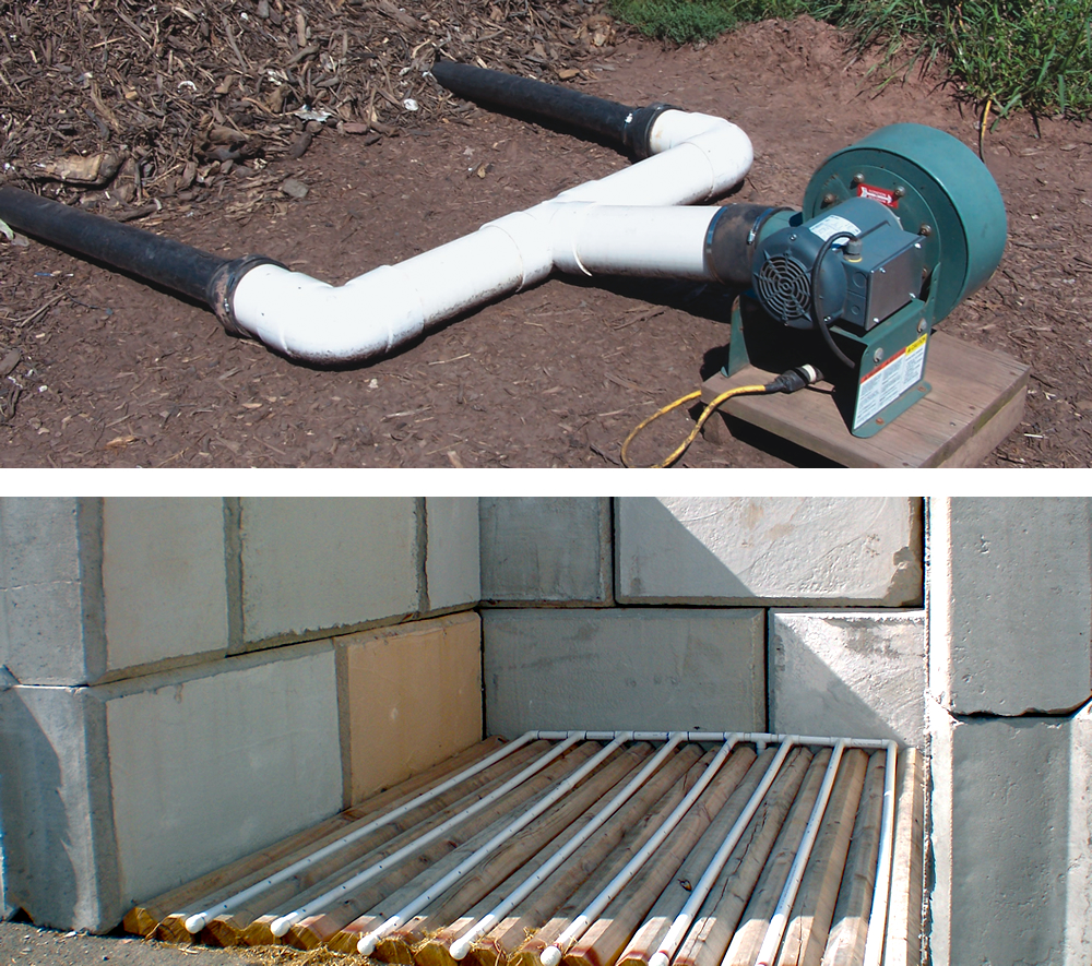
Facilities can test various piping system designs, such as entrenching the pipes as shown in this pilot test (top). ASP composting designs most often use centrifugal blowers (bottom), as these are recommended for systems with back pressure caused by having long runs of piping or ducting
Piping System Design
The aeration system design process typically starts with the piping system. While systems with pipes and ducts of all different sizes manifolded and running everywhere may look complex, a few basic starting points and rules of thumb simplify the process. Start with the pipes in the ASP and biofilter; these are usually 3- or 4-inch pipe size, spaced 4 feet apart running parallel through the pile. The 4-foot dimension is an industry standard that allows for adequate air distribution in the pile. These pipes can lie on the ground unsecured for a temporary or alterable arrangement or be placed in troughs in a concrete floor for a permanent system.
The main choices for pipe material include polyvinyl chloride (PVC), polyethylene (PE) and flexible corrugated PE. All three are commonly used in ASP composting, often mixed together at the same facility. PVC and PE are different animals, as they come in different lengths and use different methods of joining, so it pays to shop around to determine prices and availability. Many people like PVC because it’s available at big-box hardware stores, and they’re comfortable with solvent-welding sections together (the solvent essentially “glues” the pipes together via a chemical reaction). PE pipe comes in 40-foot lengths, which can be more conducive to ASP lengths — which tend to be 2 to 4 times longer than they are wide — while PVC comes in 20-foot sections. It is common to see flexible rubber couplings, secured with hose clamps, joining sections of either PVC or PE pipe, as these can handle some misalignment.
Aeration piping can be disposable or permanent. Flexible corrugated PE pipe, similar to that connected to the drain spout on a house, offers a disposable option that gets replaced with every composting cycle. It costs about $0.55/ft. Surface-mounted permanent PVC or PE pipes are pulled out and set aside at the end of a cycle while the loader tears down the pile. Entrenched piping (PVC or PE) is left in place without fear of mangling during teardown, though it does get cleaned and reused for the next cycle. The 4-inch PVC pipe sells for $3.54/linear foot (lf) while 4-inch PE pipe is $3.28/lf. The choice of whether to use disposable, surface-mounted permanent piping versus entrenched permanent piping depends on the facility’s budget and the level of confidence in having achieved the optimum (and more permanent) composting process. Laying pipes in concrete is the most costly option and should only be done after the process has been refined. The other two options are best if the facility is in developmental stages and might be modifying the process.
Whatever the choice of material for pile pipes, holes are drilled along their length for air to exit or enter, typically at one-foot intervals and on the underside of the pipe so they don’t get clogged with compost material falling in from above. Most installers have two holes at each location — at 4:00 and 8:00 on the pipes or close to that. The rule of thumb is that the total area of the holes should not exceed the inside area of the pipe, so air will be evenly distributed along the pipe. To help that, another convention says to gradually increase the hole size as the distance gets further from the manifold pipe (the header pipe from which the aeration pipes extend). As an example, the pipe will have 3/16th-inch diameter holes along the first third of the pipe, 1/4-inch holes along the middle third, and 5/16th-inch holes in the last third. Place a removable cap on the end of each pile pipe, as that facilitates cleaning and draining them out as necessary.
An interesting option offered by a few companies for the pile piping is a prefabricated product that has pipe with properly sized orifices already in it. It is made to be laid in concrete as part of a permanent system with the air ports lying flush with the floor, so vehicles can operate over the top of it without problems (material does fall into the upward-pointing holes and into the pipe, but these designs have a system for flushing that out). This type of aeration floor, supplied by BuildWorks, is being installed at an ASP retrofit project for the Wasatch Integrated Waste Management District in Layton, Utah.
With ASPs typically about 25 feet wide, the design may require up to five or six pipes running through the pile and connecting to a manifold pipe just outside the end of the ASP. Another pipe will extend from the center of the manifold to the blower. The constant-area rule of thumb applies here in selecting pipe sizes, i.e., the piping flow area should stay roughly the same throughout the system. Another rule of thumb: the velocity of air flowing in a pipe shouldn’t exceed 50 feet per second to avoid high-pressure losses and unacceptable noise generation.
To determine air velocity in a pipe, use the formula:
V = Q /A
where V= velocity in feet per minute, Q = air flow rate in cubic feet per minute, and A = area of the pipe in square feet. Another guide in selecting pipe size is the blower inlet and outlet size. If a blower in a forced draft system has an 8-inch outlet, an 8-inch pipe could be run from the outlet to the middle of a 6-inch manifold pipe to 4-inch pile pipes. If there are two pile pipes going into the manifold on either side of the 8-inch pipe, for a total of 4 pile pipes, the flow areas would be roughly equal — four 4-inch pipes equal two 6-inch pipes equals one 8-inch pipe.
In negative aeration systems, there is the added piping from the blower outlet to the biofilter. For short runs, this can be plastic pipe, but for longer and overhead runs, consider using ductwork similar to that used in HVAC systems. Typically a sheet metal or HVAC contractor will custom-fabricate a system. Galvanized steel is most commonly used, but thin-wall chlorinated polyvinyl chloride (CPVC) is also an option. Ducting should be round, and blower pipe is typically spiral wound.
Another complicating factor in induced-draft systems is the condensate that comes when pulling air through moist compost. Allow some means for draining it from the piping or ducting coming from the blower(s). This can consist of a drainpipe with a valve affixed to it in each low spot in the piping. If the pipe is small enough in diameter, it can be run into the side of a 55-gallon drum, near the bottom, and exit on the other side, near the top. Place a sump pump with a float switch inside the drum to remove condensate that collects.
Sizing The Blower
With the piping system tentatively designed, the next step is to calculate the head loss in the piping and ultimately size the blower required. When transporting any fluid through a pipe, including air, resistance from friction with the pipe walls and any objects in the flow path (like dampers, turns or T-connections) has to be overcome. This means more pressure has to be generated at the pipe inlet to overcome these frictional resistance losses and still have the pressure needed at the top of the ASP (positive aeration) or top of the biofilter (negative aeration), which is equal to or greater than atmospheric pressure. The formulas used are difficult to solve for pipe diameter, so first select pipe sizes and then calculate pressure drops and tweak the system in an iterative process.
Pressure drop (or head loss) calculation is based on the Darcy-Weisbach formula, which factors in friction factor for the pipe material, length of pipe, flow velocity and pipe diameter. Head loss can be calculated with this formula:
Where:
• hf is the head loss due to friction (SI units: meters (m));
• L is the length of the pipe (m);
• D is the hydraulic diameter of the pipe (for a pipe of circular section, this equals the internal diameter of the pipe) (m);
• V is the average velocity of the air flow, equal to the volumetric flow rate per unit cross-sectional area (m/s);
• g is the local acceleration due to gravity (m/s2);
• fD is a dimensionless coefficient called the Darcy friction factor.
Velocity is calculated from the flow rate of air through the ASP or biofilter in conjunction with the pipe diameter. Friction factors come from the Moody Friction Factor Chart and depend on the relative roughness and specific roughness, which are available on various charts. Corrugated HDPE disposable piping has a higher friction factor due to the corrugations than smooth-walled PVC pipe. Head loss is typically calculated in feet and converted to pressure by multiplying by fluid density and using a conversion factor for inches water gauge (in WG), the most common unit of pressure in air systems. The Darcy formula shows that head loss varies proportionally with the pipe length and diameter, but it varies exponentially with flow velocity. In other words, if the length or diameter of a given pipe is doubled, the head loss also is doubled. But if the flow velocity is doubled, the head loss is quadrupled. This is key — small increases in pipe size can dramatically reduce the velocity and therefore the pressure loss and ultimately the size of blower required and the power to run it.
Start the design and analysis process by determining the lengths of straight sections of pipe, and then for fittings and transitions, look up equivalent lengths on charts and add these to the straight lengths. For example, say the facility is using an 8-inch PVC pipe going from the blower to the biofilter in an induced draft system with an 8-foot straight section straight up from the blower to a long-sweep-radius elbow followed by a 100-foot horizontal section to another elbow, then an 8-foot drop to the biofilter manifold. A chart will indicate that the equivalent length of straight pipe for this elbow is 22 feet. That length is added twice to the straight lengths to get a total of 160 feet of pipe. Therefore 160 feet is plugged into the Darcy formula to calculate pressure loss for this segment, as shown in Table 1.
For induced draft systems, head loss on the suction side of the blower adds to that on the discharge side. In addition, the flow resistance of the ASP and biofilter for induced draft systems needs to be added in; as a rule, 6-inch water gauge is used for these. Formulas also exist for calculating the pressure drop across an orifice, in this case the holes in the pile pipes.
Simple programs for calculating head loss in component lengths of pipe are available online; calculations are run for the various sections of the piping system and then can be compiled in a spreadsheet to sum head losses, using different columns for different piping scenarios. Publications such as the “Heating Ventilating Air Conditioning Guide” have charts of friction loss in galvanized steel ducts.
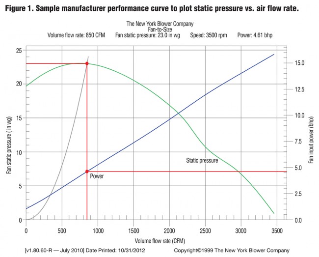
With the piping system designed and head loss calculated, it is now possible to determine a blower to use. Aeration systems most often use centrifugal blowers, as these are recommended over axial fans for systems with back pressure caused by having long runs of piping or ducting. Manufacturers publish performance curves (example shown in Figure 1) to help select an appropriately sized blower. The performance curves plot static pressure versus flow rate. Simply match the flow rate desired with the pressure drop for the ASP system designed and see if the intersection point falls along the curve along the high part of it. If so, that blower is a candidate. In the example in Figure 1, the pressure blower has to overcome 23.0 in WG static pressure and produce 850 cfm of airflow, which requires a motor with 4.61 brake horsepower (bhp).
Usually located near the manifold, the blower can be bolted to a concrete pedestal or left unattached so it can be moved around as needed. A project the authors worked on at the wastewater treatment plant in Foley, Alabama had six ASPs and blowers located outdoors, and officials requested that the blowers be located together in a shed at the middle of the row of ASPs. While this can offer some advantages, it also adds to piping lengths, increasing costs and pressure losses and subsequent energy use. When piping to a blower, try to have straight piping sections of at least four times the wheel (impeller) diameter in length at the inlet and outlet to allow the airflow to fully develop. (in the example in Figure 1, the pressure blower had a wheel diameter of 24 inches, so at least 96 inches (8 feet) of straight piping is preferred).
It only makes sense that the output of a blower varies with its speed and that the blower output should be set for optimum composting performance. There are several ways to accomplish this — either set the blower at a constant speed or constantly vary its speed. Direct drive is the simplest form of blower, as these have the motor directly coupled to the blower, which will run at 1750 or 3500 RPM. Many blowers, especially larger sizes, have a pulley-and-belt drive that can be sized to achieve the desired speed. With a variable-frequency drive (VFD), the blower speed can be varied constantly according to input from oxygen and temperature sensors in the ASP. If a constant-speed blower is selected, the main method of controlling it is to operate it with a timer that cycles the blower on and off for the desired times. Using VFDs versus timers adds a few hundred dollars of cost to each blower, not to mention the complexities of dealing with sensors and associated wires; however running the fans constantly under a VFD-controlled scenario avoids the high spike electrical costs for fans constantly turning on and off.
In this age of green building and sustainability, many industries that pump fluids through pipes and ducts in their operations are going to larger-diameter pipes that result in lower head loss due to reduced flow velocity. Following this, a smaller blower or lower blower speed can be used for composting, resulting in lower electrical power use. It helps to understand fan laws here; one says that if the speed of a blower is increased, the flow output will increase proportionally, but the horsepower required will increase by the cubed value of the change in revolutions-per-minute (RPM). For example, a blower that puts out 300 CFM at 1750 RPM will draw 0.2 BHP. If the speed is doubled to 3500 RPM, it will put out 600 CFM but draw 1.6 BHP — 8 times as much!
Of course, the added cost of the larger pipes offsets the reduced blower cost and energy use. It is useful to calculate a payback that compares higher piping costs against lower energy use and blower cost for two or more alternatives. This completes the picture and allows the facility to select the best ASP aeration system for its composting operation and feel confident in understanding how it works.
A consulting mechanical engineer, Tom Gibson is president of Tom Gibson, P.E. Green Building Engineer (www.progressiveengineer.com/consulting.html) in Milton, PA and can be reached at tom@progressiveenginer.com. Craig Coker is a Contributing Editor to BioCycle and a Principal in the firm Coker Composting & Consulting (www.cokercompost.com), near Roanoke VA. He can be reached at cscoker@verizon.net.


